Aspheric cylindrical lenses (i.e. aspheric cylinders or acylinders) have an aspheric prescription defined on a cylindrical surface to take optical performance above and beyond that of a standard cylinder optic. Just as aspheres reduce spherical aberration when focusing light into a point, acylinders provide the same benefit when focusing light into a line. Because traditional spherical and aspheric optics manufacturing techniques can’t be utilized to create acylinders, it can be challenging to produce these components cost-effectively if you are not using technology capable for the job.
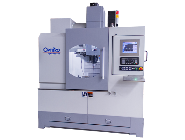
5-axis optical grinding and polishing machines have the capability of efficiently producing acylinders as long as these machines are controlled by the right computer aided manufacturing (CAM) software. OptiPro developed PROSurf™ specifically for companies interested in manufacturing complex optical components such as acylinders and freeform optics. PROSurf™ can generate precise tool paths for grinding and polishing optics. From roughing the shape out of an optical blank to corrective grinding and polishing, PROSurf™ helps optimize the entire process.
Further detail on each step of the aspheric cylinder manufacturing process is below. In this example, a 16mm wide and 200mm long acylinder was manufactured using the eSX 150 5-axis optical grinding machine and UFF 300 5-axis polishing machine. Measurement data from the OptiTrace 5000 was loaded into PROSurf™ to make metrology-driven corrections on both the eSX 150 and UFF 300.
Step 1: Defining acylinder surface in PROSurf™
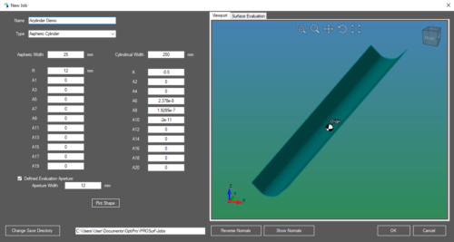
Figure 1:
Built In Common Shapes form for aspheric cylinders
The process of manufacturing an aspheric cylinder begins by defining the acylinder surface in PROSurf™. There are several input options to define a shape in PROSurf™, including:
- Solid Model (.iges or .step files)
- Point Cloud
- Mathematical Equations
- Built-in Common Shapes
The preferable method to define an aspheric cylinder in PROSurf™ is by utilizing the Built-In Common Shapes form (see figure 1). The benefit of utilizing this method is to reduce the chance of inputting incorrect information when defining an acylinder. Because aspheric cylinder equations can be complex, it is important to limit the amount of information that needs to be manually typed when entering these equations. The Built-In Common Shapes form makes it easy for the user to take the geometry as defined in a print and enter it into PROSurf™.
Step 2: Rough/fine grinding of convex acylinder
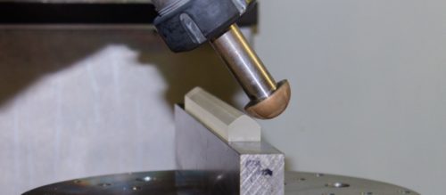
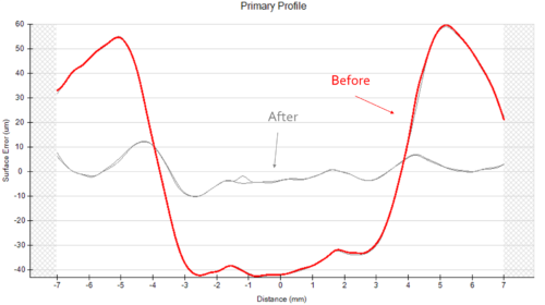
Figure 2:
Rough grind surface (red profile) – PV: 102.10 um, RMS: 39.54 um.
After single corrective grind (grey profile) – PV: 22.40 um, RMS: 4.96 um
Beginning with a rectangular blank, the convex acylinder surface is roughed out by rastering a rough ball tool over the length of the acylinder. To maximize efficiency when roughing out the shape, PROSurf™ has a feature called Rapid Material Removal. Rapid Material Removal allows you to take multiple passes in a single toolpath and automatically skip sections where the grinding tool would be air cutting. When the grinding tool reaches a section where it would be cutting air, the tool lifts up and moves to the next region where it would be actually grinding the part. The Z-height of the tool is dropped iteratively until the desired amount of material is removed.
Once the rough acylinder surface is generated, the part is measured on an instrument such as the OptiTrace 5000 contact profilometer or UltraSurf™ non-contact metrology system. In this example, a single trace on the OptiTrace 5000 was sufficient to generate a grinding correction tool path in PROSurf™. After running the grinding correction tool path using a fine ball tool, a subsequent measurement was taken on the acylinder to see if the surface specifications were adequate for UFF polishing (as was the case with this example – see figure 2).
50mm ball tools were used for rough and fine grinding the convex acylinder surface shown above. The rough ball tool had a grit size of 220, while the fine ball tool had a 10-20 grit size.

Step 3: Sub-aperture polishing of convex acylinder
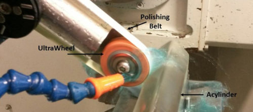
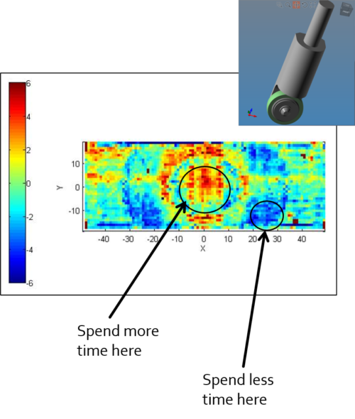
Figure 3:
Form error map with indicators showing where the UFF tool will spend more time and less time when performing metrology-driven figure corrections.
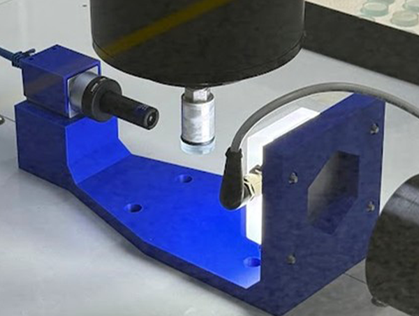
Due to the complex nature of aspheric cylinders, a machine with 5 axes of motion is necessary to perform metrology-driven figure corrections. With an acylinder, this is done by raster polishing along the length of the surface with a sub-aperture polishing tool such as UltraForm® Finishing (UFF). UFF tool configuration involves a belt of polishing material is wrapped around a compressive wheel. The belt moves at a certain RPM depending on how much material needs to be removed.
Metrology-driven figure corrections with UFF are based on dwell times, meaning the polishing tool will spend more time on the areas of the form error map where there are high spots (more error) and less time on low spots where form error is minimal (see figure 3). Dwell times are calculated using three different factors: removal rate, polish depth, and correction percentage. Removal rate is determined by taking a sample spot on a sacrificial piece of material. Polish depth is how much material you are going to take off uniformly across the surface in addition to the material taken off preferentially based on the error map. Correction percentage is simply how much form error you are looking to remove in a given toolpath. 100% correction in one pass is ideal, but it may not be possible to maintain a constant removal rate due to the size of the part, the roughness of the surface, and the belt being utilized. Because of this, several passes may be necessary to achieve 100% correction.
For our 200mm acylinder, the fine ground surface was measured on the OptiTrace 5000 and the metrology data was imported into PROSurf™ to gray out the surface with UFF. After graying out the surface, multiple traces were taken with the OptiTrace 5000 on different sections of the part. These traces were imported into PROSurf™ and stitched together to create a form error map. This form error map was used to run an additional polishing correction tool path to achieve a higher precision surface. The gray out run and polishing correction were performed with a UFF tool that included a Cerium Oxide belt and a 40mm UFF wheel.
Step 4: Additional polishing correction runs and final metrology
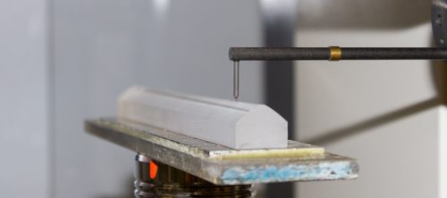
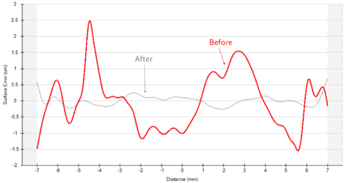
Figure 4:
Initial surface after gray out (red profile) – PV: 4.02 um, RMS: 0.87 um
After first polishing correction (grey profile) – PV: 0.95 um, RMS: 0.15 um
After running the first polishing correction, the surface is measured again to see if the form error specifications have been achieved (see figure 4). If the surface has met or exceeded the required level of precision, a final metrology report can be exported in PDF format. If another polishing correction needs to be made, the operator repeats the steps of exporting the form error traces out of the profilometer and importing them into PROSurf™ for figure correction.
OptiPro’s 5-axis optical grinding and polishing machines are engineered to help companies succeed when taking on optics jobs that involve complex geometries and precision surfaces. PROSurf™ CAM software helps maximize the capability of these machines by generating precise toolpaths and performing metrology-driven figure corrections. Partner with OptiPro on your next acylinder or freeform optics manufacturing job to meet your production requirements. Contact our team today for more information and to find the right machine(s) for your application.