Freeform optics are complex components that offer greater performance than spherical lenses and aspheres by overcoming the limitations in rotationally symmetric optics. One freeform optic can often replace several lenses in an optical system. Because freeforms are non-rotationally symmetric, they do not have an axis of rotation to spin the optic about during manufacturing. This poses a challenge when making these components, since these shapes cannot be manufactured with methods typically used for rotationally symmetric optics. To produce freeform optics cost-effectively, OptiPro has made constant enhancements to their CNC optical grinding technology and sub-aperture polishing system UltraForm Finishing (UFF). In addition, OptiPro introduced PROSurf in 2015. PROSurf is a freeform CAM software that generates more precise toolpaths for freeform optics than traditional CAM software packages. PROSurf also supports metrology-driven corrections when grinding and polishing freeform optics. Using customer feedback, several updates to PROSurf have been made since its initial release to optimize the freeform optics manufacturing process. This process consists of four steps involving three OptiPro machines: a 5-axis CNC optical grinding machine to generate the freeform surface, a 5-axis UFF machine to polish the surface to the desired quality, and the UltraSurf 5X 400 non-contact metrology system to perform in-process and final metrology. Below is a detailed description of all four stages in the freeform manufacturing process with an ellipsoid being produced out of optical glass on the eSX 150 CNC optical grinder and UFF 300 freeform polishing machine.
Step 1: Freeform surface generation
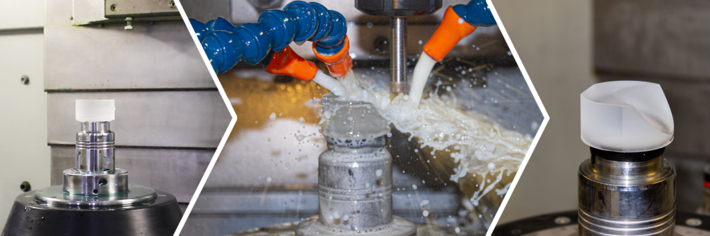
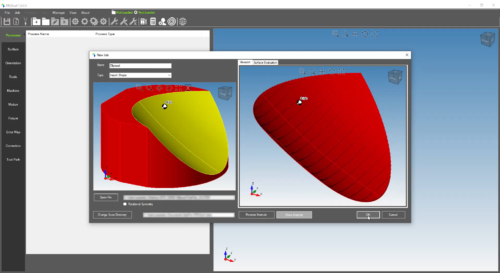
Figure 1: Freeform surface defined in PROSurf by importing a CAD model.
To manufacture a freeform optic, it is necessary to initially “rough out” the surface from an optical blank. To do this, the operator must first define the surface in a CAM software, such as PROSurf, by importing a CAD model, an equation, or a point cloud of the surface (see figure 1). After defining the surface, a rapid material removal toolpath can be generated by entering tool and process parameters into PROSurf. With rapid material removal enabled, PROSurf can program bulk material removal to a specified amount of stock by having the tool start with the flat top of the blank and rough out the entire surface. This method maximizes cut efficiency by skipping over any motion where the tool would be cutting air, effectively reducing cycle times and increasing efficiency. Once the rapid material removal toolpath is generated, it is saved on a computer separate from the machine since PROSurf is an offline program. The toolpath is then moved over to run on a CNC optical grinding machine, such as the eSX 150, to create a near net shape of the freeform surface that is suitable for rough grinding.
The ellipsoid above was defined in PROSurf using a CAD model. The surface was generated on the eSX 150 using a 12.7mm diameter ring tool with a 180 grit size.
Step 2: Rough/fine grinding of freeform surface
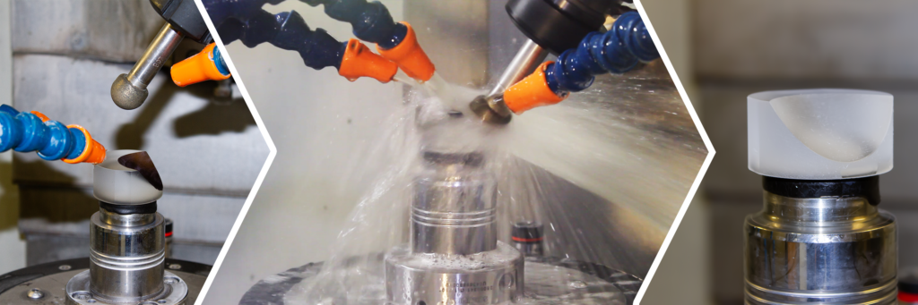
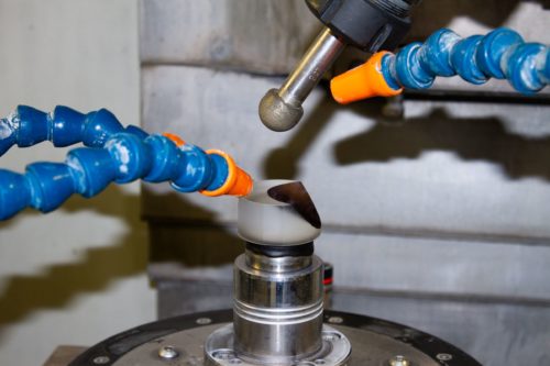
Figure 2: Ball tools were utilized to rough and fine grind the ellipsoid surface. Before processing, the surface was covered with a black marker. This is common when grinding and polishing optics to ensure consistent material removal across the surface.
The second step involves using a ball tool to rough grind the freeform surface (see figure 2). After importing a CAD model of the freeform surface, the parameters of the tool and process are entered to generate the initial rough grind toolpath. The rough ball tool will contour starting at the bottom of the surface and work its way toward the top. The cycle is completed when the tool makes its last roughing pass at the top of the surface. After the surface has been completely roughed in, the part is removed from the machine to be measured on a metrology system capable of measuring freeform surfaces, such as the UltraSurf 5X 400. Using the error map from this measurement (see figure 3), another rough grinding toolpath is created in PROSurf and run on the optical grinder. Metrology-driven corrections are repeated until the surface error is adequate for fine grinding.
The fine grinding process uses the same sized ball tool with a finer grit and involves the same workflow as rough grinding:
- Set up the point distribution for the toolpath with the fine grit tool
- Enter tool and process parameters to generate a toolpath
- Load the toolpath in the CNC control and run the program on a 5-axis optical grinding machine
- Remove the initial fine ground surface from the machine and measure on the UltraSurf 5X 400 to create an error map
- Perform correction toolpath to produce a more precise fine ground surface
- If necessary, repeat metrology driven correction runs until the surface is ready for polishing
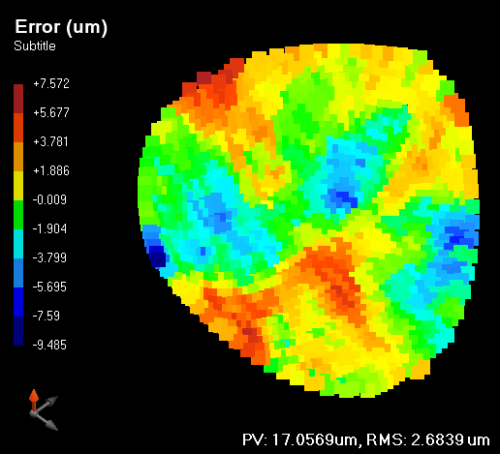
Figure 3: Error map after measuring the fine ground ellipsoid surface on the UltraSurf 5X 400.
For our ellipsoid surface, a 25.222mm diameter ball tool with a grit size of 220 was used for rough grinding. The same size ball tool with a 1200 grit size was used to fine grind the ellipsoid surface.
Step 3: Sub-aperture polishing of freeform surface
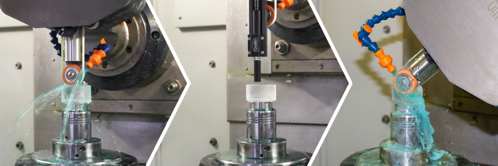
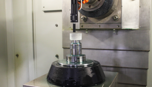
Figure 4: “Spot” part being measured with on-board probing on the UFF machine to calculate removal function.
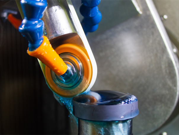
After fine grinding the freeform surface, the freeform is polished on a 5-Axis CNC machine that utilizes a sub-aperture polishing process, such as the UFF 300. Sub-aperture polishing is when the polishing body is small in comparison to the size of the surface. UltraForm® Finishing (UFF) involves a belt of polishing material (polishing body) moving at a certain speed (in rotations per minutes) which is wrapped around a compressive wheel. The key to UFF’s efficient polishing capability is maintaining constant removal over the entire surface by having an accurate removal function. With UFF, the removal function is created by “taking a spot”, which means polishing a spot on a sacrificial part that has the same characteristics of the fine ground freeform surface. The spot is then measured using the UFF’s onboard metrology (see figure 4). Subsequently, U Series, the polishing software that runs all UFF machines, calculates the removal function by calculating the volumetric removal rate based on belt speed, wheel durometer, compression, and dwell time.
The initial UFF toolpath to gray out the surface is then generated (see figure 5). This is done by adding a polishing process in PROSurf, entering the parameters of the UFF tool, then entering the process parameters including volumetric removal rate and polish depth from the spot part. Once the surface is polished and the residual grinding marks have been removed, the freeform optic is moved to the UltraSurf 5X 400 for measurement.
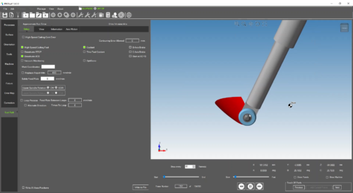
Figure 5: UFF Toolpath simulation in PROSurf to ensure optimal polishing cycle.
Freeform polishing of the ellipsoid required a Cerium Oxide belt and a 40mm 50 durometer UFF wheel on the UFF 300 5-axis polishing machine.

Step 4: Metrology-driven correction runs and final metrology
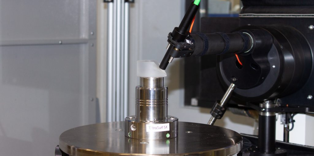
To perform a correction run on UFF, the freeform is first measured on the 5-axis UltraSurf. Once the measurement is complete, the error map can be exported out of UltraSurf in several different file formats. The user creates a new polishing process in PROSurf to differentiate the gray out parameters from the corrections parameters. In this process, the correction file is imported into PROSurf. After loading the error map, a correction toolpath is generated and run on the UFF 300. Once the first polishing correction run on UFF is complete, the freeform is measured again on UltraSurf to determine whether another correction run is necessary or if the specified surface irregularity is achieved. If the freeform surface has reached an acceptable level of precision, a final metrology report can be exported out of UltraSurf in PDF format.
With several machine suites for different diameter sizes, OptiPro can help add efficiency to your freeform manufacturing process. Contact our team for consulting and let’s collaborate on your next freeform optics manufacturing project.