Aspheres are defined as rotationally symmetric optics with a surface that deviates from the best fit sphere (bfs). This deviation can be small or significant, depending on the asphere’s application. To produce aspheres cost-effectively, OptiPro was the first company to introduce CNC optical grinding technology in the early 1990’s as well as a patented UltraForm Finishing (UFF) process in the late 2000’s to the precision optics market. Constant enhancements to the hardware and software of these machines have allowed companies to achieve faster job setups and cycle times to optimize the asphere manufacturing process. This process consists of four steps involving three OptiPro machines: the aforementioned CNC optical grinder and UFF platform, as well as an asphere metrology instrument such as the OptiTrace 5000 surface profilometer or UltraSurf 4X 300 non-contact metrology system. Each step is explained in further detail below with an example showing a 200mm asphere with radical departure being processed in the PRO 160 GTS CNC optical grinder and PRO 160 UFF asphere polishing machine.
Step 1: Spherical surface generation
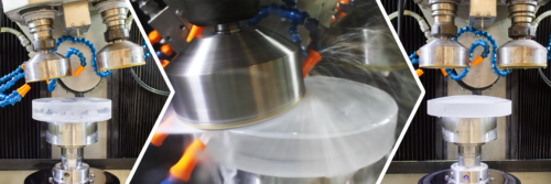
The first step in the asphere manufacturing process is to generate the spherical surface from an optical blank. This is done by programming the CNC optical grinder to tilt the rotating ring tool at a certain angle, depending on the optic’s radius of curvature, and feed it into the blank. The inside diameter of the ring tool is used to generate convex spherical surfaces, while the outside diameter of the tool will engage with the part when generating concave spherical surfaces. G Series, the lens grinding software that controls the PRO 160 GTS as well as all other OptiPro grinding machines, can be easily programmed to generate spherical surfaces.
Generating the convex spherical surface for our 200mm asphere shown above required two 120mm diameter ring tools – the ring tool for the rough grinding cycle had a grit size of 220, while the fine grinding ring tool had a 1200 grit size.
Step 2: Rough/fine grinding of aspheric surface
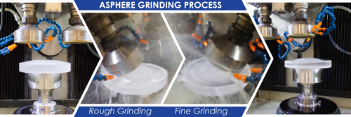
The second step involves using a ring tool, ball tool, or grinding wheel to contour the aspheric deviation into the best fit sphere. The CNC optical grinder is programmed to have the rough tool contour the aspheric surface by starting at the edge of the optic and moving toward the center. Once the tool reaches the center of the optic, the cycle is finished and a rough aspheric surface is created. Then, the same operation is repeated, but this time with a fine tool to create a fine ground aspheric surface. If using a twin spindle grinding machine, such as the PRO 160 GTS, these two operations can be programmed in G Series to run in one cycle. Otherwise, a tool change is necessary, either by using an automatic tool changer or by manually switching the rough grinding tool with a fine tool.
For our 200mm asphere job, the same two ring tools were used for grinding the aspheric surface as was used during spherical generating. Because we ran this asphere in the PRO 160 GTS, we were able to chain the rough and fine grinding operations together in one cycle for added efficiency.
After fine grinding the asphere, the surface needs to be measured using an on-board probing routine, if available, or by removing the asphere from the machine and measuring the surface on a metrology instrument such as the OptiTrace 5000 or UltraSurf 4X 300. Typically, at least one correction run will need to take place to achieve an adequate surface quality that will allow for sub-aperture polishing.
Step 3: Sub-aperture polishing of aspheric surface
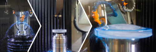
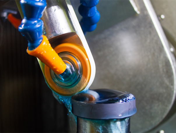
After the fine ground aspheric surface has been generated, the asphere will be polished using a CNC machine that utilizes a sub-aperture polishing process, such as the PRO 160 UFF. Sub-aperture polishing is when the polishing body is small in comparison to the size of the optic. UltraForm Finishing (UFF) involves a belt of polishing material (polishing body) moving at a certain RPM which is wrapped around a compressive wheel. The key to UFF’s efficient polishing capability is maintaining constant removal over the entire surface by having an accurate removal function. With UFF, the removal function is created by “taking a spot”, which means polishing a spot on a sacrificial part that has the same characteristics of the actual asphere. The spot is then measured using onboard metrology. Subsequently, U Series, the polishing software that runs all UFF machines, takes the removal function, as well as other information including initial surface quality, and creates an optimized tool path that will yield a polished aspheric surface. Another sacrificial spot part that is already fine ground is then polished in UFF using the removal function of the first spot part. A spot is then taken on this second polished part to create another removal function. These two removal functions will be applied to each asphere being polished. The initial polishing cycle using the first removal function will gray out the part, or remove bulk material from the fine ground surface. Once the surface is polished to remove bulk material, a second polishing cycle using the second removal function will yield a higher precision surface.
When polishing the 200mm asphere, we used a Cerium Oxide belt and a 40mm UFF wheel on the PRO 160 UFF. While the PRO 160 UFF is spec’d to do part diameters up to 160mm, the machine can run certain aspheres up to 200mm depending on geometry.
The asphere now needs to be measured on a profilometer or non-contact metrology system such as the UltraSurf 4X 300 to see if a correction run is necessary.
Step 4: Metrology-driven correction runs and final metrology
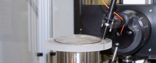
To perform a correction run on UFF, you first need to measure the asphere on the UltraSurf 4X 300 non-contact metrology system. Once the measurement is complete, the metrology data can be exported out of UltraSurf in several different file formats, then imported into U Series to optimize the tool path for a correction run. After running a correction cycle on UFF, the asphere is measured again on UltraSurf to determine whether another correction run is necessary or if the asphere’s surface quality is adequate. Once the surface has reached an acceptable level of precision, a final metrology report can be exported out of UltraSurf in PDF format.
With several machine suites for different diameter sizes, OptiPro can help add efficiency to your asphere manufacturing process. Contact our team today for more information and to find the right machine(s) for your application.